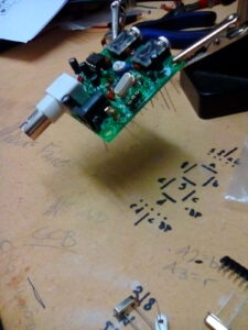
Testing the Pixie II

It’s Alive!

Chinese Pixie II
My new Chinese Pixie II fully assembled and nestled in it’s Altoids tin enclosure.

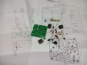
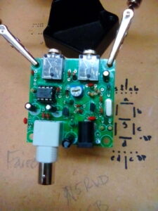
Okay! I just got to test the receive part of the Pixie II… and it worked!! This is the first fixed frequency radio I’ve ever built or even heard, so I have no basis for comparison, but I can tell you that it worked and that is very exciting for me. I thought it was cool when I built a little ground plane antenna for 2m and then a 5/8 wave whip for my 2m radio, but this is really something. I know I didn’t design the radio, but just the idea that I built it from a bag of parts, put it in an Altoids tin, hooked it up to a dipole antenna that I made from some speaker wire, and heard real, live CW is amazing! To me, this is what ham radio is about. And I can’t wait to finish my next radio project of redesigning and building a variation of the qrpme.com’s Sea Sprite (which is just an improvement on the Pixie II).

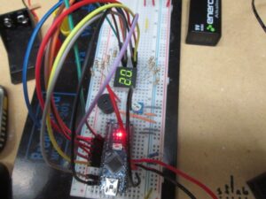
Testing Different Frequencies

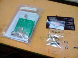
I went through the crystals from the 8-pack (plus the one that came with the Pixie II) and picked up transmissions on 7.030, 7.040, 7.050, 7.070 and 7.110. The first 2 probably came through the clearest, but 7.110 came through well enough for me to catch some if it. And that’s important since it’s the novice frequency and will probably be the frequency I call on first. There’s a good reference for QRP at QRP Portal. Here’s the calling frequencies chart from their site:

40m
7.003
CW
(Japan, daytime only!)
7.028
CW
VK VK3YE
7.030
CW
(Europe) AC6V, ARRL, GQRP, K3WWP, NJQRP, RU-QRP, VK3YE
7.035
CW
(QRP-L) AC6V
7.040
CW
(US) AC6V, ARRL, K3WWP, NJQRP, VK3YE — now moving to 7.030
7.060
CW
(Europe) AC6V, NJQRP
7.090
SSB
(Europe) GQRP, NJQRP, RU-QRP
7.110
CW
US Novice AC6V, ARRL, K3WWP, NJQRP
7.285
SSB
AC6V, ARRL, NJQRP

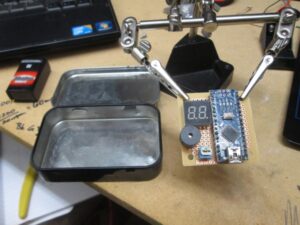
So 3 out of 5 are primarily CW frequencies, 7.070 is PSK31 for regions 1 and 2, and I guess 7.050 is CW and digital modes. While I was able to pick up some transmissions, boy was that confusing! It’s going to really take some work to pick out a single station. They’re all stacked on top of each other! I probably heard 4 or 5 different stations on every frequency I picked up. Fortunately for me, I built a little 1/2 watt audio amplifier I built a little while back that worked great with the Pixie II. Though I was able to hear the stations with regular headphones, the amplifier really helped to pick out the individual stations.

Now I just need to find the time to finish learning CW and play with my new toy. I think a CW decoder may be in order for practice.

Chinese Pixie II 40m QRP Kit

My Chinese Pixie II 40 meter QRP kit and 40m crystal set finally arrived!

The Pixie II 40m CW QRP kit and 40m crystal QRP calling 8-pack that I ordered from EBay just arrived in the mail! I can’t wait to be done with work so I can get started assembling it! Unfortunately, I’m self employed so I work ridiculous hours pretty much every day. Boo.

I ordered a 40m crystal 8-pack (pictured below) to get the major US 40m QRP calling frequencies. I was glad to find that it came with a SIP socket strip to use for the crystal socket. And I still have to figure out an antenna for it. I think something like the doublet dipole out of speaker wire, but I’m not sure how to connect it to BNC. I’ll probably end up using a simple wire connector since I don’t plan to use coaxial cable.

Pixie II and 40m crystal set
This is what came in the mail today! My new Chinese Pixie II 40m QRP and 40m crystal set
The complete Pixie II packaging
Everything that came in the package. The full schematic, BOM reference, PCB and all the components and connectors.
Pixie II PCB
The Pixie II Printed Circuit Board. Component placement is labeled with standard schematic alphanumerics. The included reference sheet is required to know what to put where.
Pixie II conponent placement
Pixie II component placement. Nothing is soldered yet.
Pixie II component placement with SIP socket
Component placement showing the SIP socket used as a crystal socket.

As soon as I opened the kit, I was pretty impressed. I was a little surprised to find a full schematic of the Pixie II and “instructions” included with the kit. Normally, these kits come with just a PCB labeled with values and a bag of parts. The PCB is legit thru hole and small enough for the infamous and much talked about Altoids tin and is clearly labeled to be referenced to the bill of materials sheet that came with it. I can’t wait get on the air with it and I got it just in time for ARRL Field Day!

Homebrew QRP (CW or SSB)

I’ve been getting frustrated trying to find complete/useful information on building a radio from scratch. All of the designs I find are really old and have parts that are hard to find now or are new and really complex. I realize that the transmission standards are higher now, but is there no middle ground? I’m looking for simple with modern and easy to find (read cheap) parts.

It would seem that QRP CW is my answer for now. I’ve found some homebrew QRP SSB, but I’m not sure I’m ready for that. Possibly the best resource I’ve found to this end is qrpme.com. They have lots of cool little QRP rigs and accessories to choose from ranging from about $30 up to about $50. I’m looking at the Lil’ Squall II that’s based on the infamous Pixie II, but with a crystal socket and changeable lowpass filter. It’s still fixed frequency, but you can easily change the crystal and filter and jump to other frequencies or even whole different bands. This kit is so simple and so well documented, that I’m going to attempt to build it from parts that I source myself whether from scavenging from other stuff, my local Hackerspace or ordering from EBay. I’m hoping to keep my cost well below the already inexpensive kit.

I’m also looking at the Rockmite II kits on the qrpme.com site. I will probably end up just ordering one of these kits when I can save up the $50 and justify spending it on a radio.

Another possible solution that recently caught my eye is the Arduino/AD9850 DDS combination that may allow one to build a VFO radio for less than $30. That sounds pretty cool. I’ll have to do some more research on this to see if it’s what I think it is. I’m not really sure what this would be capable of. If it would pick up and send CW, that would be cool enough for me. If it can also be used as part of AM, DSB, SSB or whatever, that would be rad.

Morse Mentor for Android

Slowly but surely in still learning Morse code. I’ve been using lcwo.net, but I’ve discovered that that is really limiting my potential practice time. I haven’t tried many apps, but Morse Mentor seems to offer most of the same features as lcwo. Koch method, Farnsworth timing, etc. I’m working with character speed at 20wpm, but Farnsworth of 5wpm. I’m doing well at that speed, but I know I’ll have to speed it up a lot to get on the air. I hope to be proficient at cw and have a QRP rig built by the time I go to Burning Man this year. Oh and I hope to get my general class ticket!

CW is difficult for me

I’m using lcwo.net, but I’m having real trouble copying at 20 WPM characters with 5 WPM spacing (effective 10 WPM). I think part of the problem is that I have trouble recovering when I miss a character. I just kind of spaz out. Now, I haven’t been sticking with any schedule let alone daily practice, but I’m determined to get it. I really need an HF receiver and antenna so I can listen to other beginners.

The Hackey Iambic Key

This is the homebrew iambic key, Hackey,  origianally from N4SER.
This is the homebrew iambic key, Hackey, originally from N4SER.

Hackey Parts list:

  • old hacksaw blade (duh)
  • 4x corner brackets
  • 2x 1″ 6-32 machine screws
  • 2x 1/2″ 6-32 machine screws
  • 6x 6-32 nuts
  • 8x #6 1/2″ wood screws
  • a screw that is the height of the hacksaw blades
  • some wire
  • 3.5mm audio jack

On my quest for a better understanding of the hardware involved with learning CW, I started finding come cool homebrew keys. The one that really stuck out for me was The Hackey. It not only shows how simple a key can be, but it’s made from found stuff. Perfect!

The center post/screw is the common ground and the 2 halves of the hacksaw blade are the contacts. The long screws toward the front adjust the distance of action and the screws in the back just hold the contacts in place and connect the dit and dah wires.

This is a simple, fun and satisfying afternoon project.

Some Basics of CW Hardware

It seems like hams assume a lot with terminology/jargon. One point of confusion for me was what exactly the parts were for even a simple CW practice setup would be. The words I kept seeing were key, paddle, iambic, keyer and oscillator. Here is what I finally concluded (though my conclusions may not be 100% accurate).

There is an excellent article (as with so many topics) on Wikipedia titled Telegraph Key. It covers the straight key, bug, and iambic key.

I’ll start with the simplest which is just a straight key. In this case, the key is just a simple switch that closes and opens the circuit. When the circuit is closed, you are sending, then it’s open, you’re not. That makes the dits and dahs. With a straight key, the user controls the length of the dits, dahs and spacing. Convention is that the dah is equal in length to three dits with a dit spacing between letters. That’s a lot of to deal with especially when you’re just learning. Plus modern hams seem to hate it when people get on the air with a straight key. They’re slow and hard to copy.

I’m still not entirely sure what a bug is, but they don’t seem terribly popular so I didn’t really look into them. It seems to be a mechanical paddle key that performs some of the same functions as an electronic keyer. Like I said though, unless you’re into the nostalgia and evolution of CW, you can probably skip the bug.

Next up is the paddle. This is where it starts to get fun and nerdy. I haven’t seen a lot of these since people seem to go straight to iambic keying when setting up an electronic keyer. So a single paddle, as with an iambic key, there are two switches and a common ground.  With a paddle, the paddle itself is the common ground and the operator moves it side to side to the dit and dah contacts. When one switch is closed, the keyer makes a dit, repeatedly, with proper spacing; when the other is closed, the keyer makes a dah. So, then, what is a keyer? A keyer is a little electronic device that actually generates the tone, tone length and spacing. Of course you can just search and find an already built keyer that does all kinds of stuff for you, but where’s the fun in that? There are wildly varying plans for them all over the internet, but unless you’re one of the lucky ones that lives in a town with something more than Radio Shack, you’ll have to order parts. And wait. I chose to make my keyer out of an Arduino Nano, some parts from Radio Shack and stuff I found. More on that in the Arduino CW Project series.

A step further is the iambic key. This key has 2 paddles, one for dit one for dah. There is a central contact that acts as the common ground and each paddle is a switch for the dit or dah. But with an iambic keyer, when you squeeze the two paddles together, it will alternate between dit and dah with proper spacing. This is really cool, but will take practice. For myself, I built an iambic key, but have not implemented the iambic functionality to the software on the Arduino based keyer. I’ve only just started learning morse code, so I’m learning with just the basic keying. Maybe this is counter productive, but I’d like to be able to use both a regular paddle and an iambic key.

If you have any questions or corrections for this article, please ask. Teaching and helping others is a great way to learn, and ham radio is a social hobby. Please refer to my Arduino CW Project series.

Arduino CW Project: part 1

Keyer Parts list:

  • Arduino Nano (or compatible)
  • Piezzo buzzer
  • 10K ohm trim potentiometer
  • 8x 100 ohm 1/4 watt resistors
  • 2-digit seven segment display (SSD)
  • 9 volt battery
  • 9 volt battery cap
  • 10x jumpers
  • 3.5mm audio jack
  • some extra solid wire for short connections

I was so excited when I got the Arduino Nano, I had the headers  soldered and on the breadboard for a CW keyer the same night I got it. I didn’t get the 2-digit seven segment display (SSD) installed until a couple days later. Now I’ve got that wired up and working as it should and with a more logical wiring layout than I did when I got it working before. This will be significant later.

I started with the tutorial and code for seven segment displays I found over at Tinker Hobby. With a little work and some judicious note taking, I was able to map my common anode SSD and get the counter program working right. From there, I needed to figure out how to output my WPM (Words Per Minute) to the SSD. You can easily use Serial.println() to output WPM to the debug window in the Arduino IDE, but that’s not very portable. To get your words per minute, you’ll need a little math (but not much really). You already have the millisecond length of the tone from the sketch. Just divide 1200 by the milliseconds and you’ve got your approximate workds per minute. A little tip here (and you’ll see this in the sketch) is to divide down the milliseconds so that the potentiometer adjustment isn’t so sensitive.

Okay. So now you have your WPM. How do we get it to the SSD? It’s not as hard as you’d think. We start by breaking up the digits of your WPM. We have to do this because the SSD doesn’t actually display both digits simultaneously. What’s really happening is that one digit gets displayed, then the other, really fast. So that’s what we’ll do. To separate the digits, we’ll use the modulo operator that performs a simple division and returns the remainder. You can see how this is done in the sketch. You may have to experiment a little to get how the pins are laid out on your SSD. The segments are always the same. You can change the mapping in the definitions section of the sketch.

Now you just follow the schematic, write the sketch to the Arduino and you should have a working, adjustable keyer with side tone and a handy readout.

Nano with everything wired up for testing.

Nano with everything wired up for testing.

You can see the Arduino Nano at the bottom with the power LED lit up. I’m running the project off of a 9v battery on the VIN (Voltage IN) and ground. The wiring on the right side of the board — the analog pins — is for the keyer. A0 is set as input from from the 10k ohm trim pot, A1 is output to the piezo speaker for sidetone, and A2 and A3 are the dit and dah for the Hackey. The SSD is hooked up the the digital pins.