Keyer Parts list:
- Arduino Nano (or compatible)
- Piezzo buzzer
- 10K ohm trim potentiometer
- 8x 100 ohm 1/4 watt resistors
- 2-digit seven segment display (SSD)
- 9 volt battery
- 9 volt battery cap
- 10x jumpers
- 3.5mm audio jack
- some extra solid wire for short connections
I was so excited when I got the Arduino Nano, I had the headers soldered and on the breadboard for a CW keyer the same night I got it. I didn’t get the 2-digit seven segment display (SSD) installed until a couple days later. Now I’ve got that wired up and working as it should and with a more logical wiring layout than I did when I got it working before. This will be significant later.
I started with the tutorial and code for seven segment displays I found over at Tinker Hobby. With a little work and some judicious note taking, I was able to map my common anode SSD and get the counter program working right. From there, I needed to figure out how to output my WPM (Words Per Minute) to the SSD. You can easily use Serial.println() to output WPM to the debug window in the Arduino IDE, but that’s not very portable. To get your words per minute, you’ll need a little math (but not much really). You already have the millisecond length of the tone from the sketch. Just divide 1200 by the milliseconds and you’ve got your approximate workds per minute. A little tip here (and you’ll see this in the sketch) is to divide down the milliseconds so that the potentiometer adjustment isn’t so sensitive.
Okay. So now you have your WPM. How do we get it to the SSD? It’s not as hard as you’d think. We start by breaking up the digits of your WPM. We have to do this because the SSD doesn’t actually display both digits simultaneously. What’s really happening is that one digit gets displayed, then the other, really fast. So that’s what we’ll do. To separate the digits, we’ll use the modulo operator that performs a simple division and returns the remainder. You can see how this is done in the sketch. You may have to experiment a little to get how the pins are laid out on your SSD. The segments are always the same. You can change the mapping in the definitions section of the sketch.
Now you just follow the schematic, write the sketch to the Arduino and you should have a working, adjustable keyer with side tone and a handy readout.
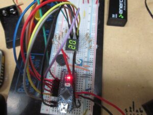
Nano with everything wired up for testing.
You can see the Arduino Nano at the bottom with the power LED lit up. I’m running the project off of a 9v battery on the VIN (Voltage IN) and ground. The wiring on the right side of the board — the analog pins — is for the keyer. A0 is set as input from from the 10k ohm trim pot, A1 is output to the piezo speaker for sidetone, and A2 and A3 are the dit and dah for the Hackey. The SSD is hooked up the the digital pins.